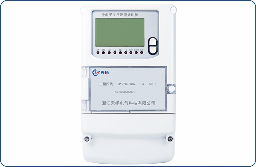
Full electronic voltage-output breaking timer (liquid crystal display) This product is used to monitor the operating status of three-phase three-wire (three-phase four-wire) active (reactive) meter, whenPT When the circuit (primary or secondary) is blown or completely disconnected, CT When the circuit is open, the instrument will accurately judge the phases of the voltage loss voltage and the open current, and record the corresponding time in detail (or kWh), The product also has infrared communication function and can be connected RS485 Meet customers' remote data transmission quickly, so as to help the power metering department manage the power grid and compensate for artificial or non-artificial leakage of electricity.when PT When the circuit phase sequence is reversed, the instrument can issue a prompt, which is of great significance to strengthening power consumption management and improving the metering level. It is the most ideal electrical energy metering monitoring instrument.
Main functions
1.Loss of pressure timing
When the voltage loop (PT)When pressure loss occurs, the faults can be judged accurately in a timely and accurate manner and the accumulated time during the fault is recorded.If connected outside
If the active power pulse input is input, abnormal electrical energy during the failure can be recorded simultaneously.
2.Disconnection timer
When the current loop (CT)When a current breakage (refers to the electrical open circuit) or a current loop loss (refers to the circuit current being less than the dynamic current), it can be accurate in time
Verify the difference between the fault and record the accumulated time during the fault.If an external active power pulse input is connected, the fault period can be recorded at the same time.
Abnormal power.
3.Fault power record
When the instrument is connected to the active power (active) pulse input, the faulty power can be accurately recorded in phases and provided a reference for power compensation.
4.Recording of failure times
When the voltage loop (PT)Loss voltage occurs, current loop (CT)When an open circuit occurs, the internal fault count counter is started, and the voltage loss is recorded.
Number of times or number of interruptions.It is an auxiliary parameter.
5.Event loggingThis instrument can timely record the start date, start time, end date and end time of pressure loss and interruption in the order of event occurrence.
6.Data communication
By instrument RS485 Communication auxiliary wiring terminals can communicate data with communication terminals or host computers.
7.Voltage phase sequence indication
This instrument can indicate the inversion of voltage phase sequence caused by human or accidents.
Parameter description:
type Number | Reference voltageUn | Rated currentIn |
Three phases and three lines | 3×100V | 3×1.5(6)A |
3×3(6)A |
3×380V | 3×1.5(6)A |
3×3(6)A |
3×2.5(10)A |
3×5(20)A |
3×10(40)A |
3×10(60)A |
3×15(60)A |
3×20(80)A |
3×30(100)A |
Three-phase and four-wire | 3×57.7/100V | 3×1.5(6)A |
3×3(6)A |
3×220/380V | 3×1.5(6)A |
3×3(6)A |
3×2.5(10)A |
3×5(20)A |
3×10(40)A |
3×15(60)A |
3×20(80)A |
3×30(100)A |
Rated frequency | 50Hz |
Appearance size | 265mm´170mm´75mm |
weight | about2.5kg |
Normal working voltage | 0.8Un~1.2Un |
Extreme working voltage | 0.7Un~1.3Un |
Voltage line power consumption | ≤1.5W and 5 VA ( Auxiliary power supply ≤10VA) |
Current line power consumption | <2 VA |
Clock battery voltage | 3.6V |
Power outage meter reading battery voltage | 3.0V |
Clock accuracy(Daily error ) | ≤0.5s/d( Temperature -30 ℃~+65℃) |
Clock battery capacity | ≥1200mAh |
Data storage time after power outage | ≥10Year |
Normal operating temperature | -20℃~+60℃ |
Extreme operating temperature | -30℃~+70℃ |
Storage and transportation temperature | -40℃~+70℃ |
Storage and working humidity | ≤85%RH |
How it works:
This voltage-destruction timer is made of high-speed, low-power microcontroller, current and voltage acquisition circuit, high-precision time base generation circuit,LCD
It consists of display driving circuit, alarm output circuit, three-phase power supply circuit, data storage circuit and other parts.This instrument uses the current voltage
The acquisition of the signal and power pulses enables monitoring of the metering circuit.See Figure 1 for the working principle block diagram.
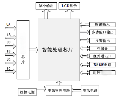
 picture1 Working principle block diagram
When the instrument is working, the voltage and current are sampled separately by the sampling circuit, and then sent to the amplifier circuit to buffer and amplify, and then converted from the metering chip to a digital signal. The high-performance microcontroller is responsible for analyzing and processing the data.Since the high-precision metering chip is used, the metering chip completes the front-end high-speed sampling by itself, and the metering algorithm is stable, the microcontroller only needs to manage and control the working status of the metering chip.Display all data as needed, through infrared or485The interface conducts communication and transmission, completes monitoring of operating parameters, and records and stores various data.